InfraLens — CAD to GIS for Water Utilities
A CAD-to-GIS workflow for transforming water utility drawings into structured, connected, and map-ready infrastructure data. InfraLens bridges engineering CAD drawings and GIS so pipes, valves, meters, and other network assets can become usable spatial information for utility operations.
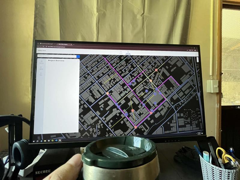
The Problem
Water utility infrastructure often starts and stays in CAD drawings.
A CAD-to-GIS workflow for transforming water utility drawings into structured, connected, and map-ready infrastructure data.
InfraLens bridges engineering CAD drawings and GIS so pipes, valves, meters, and other network assets can become usable spatial information for utility operations.
CAD works well for engineering and drafting, but as networks grow, information becomes distributed across drawings, folders, revisions, and individual computers.
This makes a simple operational question harder than it should be:
Where is the asset, what is connected to it, and which drawing contains the latest information?
The data exists—but it was created for drawing the network, not managing it as a spatial system.
Method
CAD Data Assessment
Existing utility drawings are reviewed to identify the structure of the network, CAD layers, blocks, labels, linework, coordinates, and available asset information.
Instead of treating the drawing as one map, its components are separated according to their real-world purpose.
CAD → GIS Conversion
Engineering drawings are converted into structured GIS features.
CAD Lines → Water Pipes
CAD Blocks → Valves, Meters & Utility Assets
CAD Labels → Asset Attributes
Drawing Coordinates → GIS Spatial Reference
The objective is not simply converting DWG files into GIS formats. The data is cleaned and structured so individual features represent actual utility assets.
Data Cleaning & Standardization
Converted features are checked for geometry problems, duplicates, missing attributes, inconsistent naming, and disconnected linework.
Asset information is standardized into a GIS schema so infrastructure from different drawings can eventually become part of the same utility dataset.
Network & Connectivity
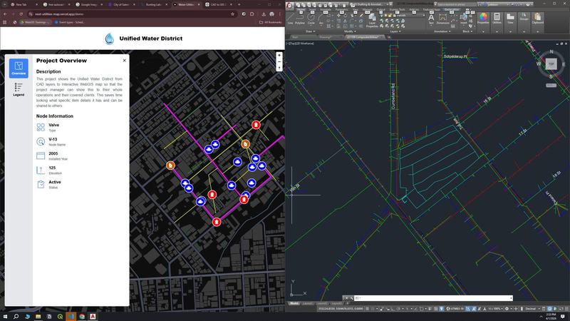
Pipe segments and utility assets are organized according to their spatial relationships.
This creates the foundation for understanding how the network is connected—not just where individual lines appear on a drawing.
GIS Mapping
The standardized network can then be viewed and maintained through GIS.
Utility personnel can explore infrastructure spatially, inspect asset information, update records, and connect field or operational information back to the network.
The overall workflow becomes:
Engineering CAD → Extract Assets → Clean & Standardize → Build GIS Network → Map & Manage
Why
CAD and GIS solve different parts of the infrastructure problem.
CAD helps engineers design and draw the network. GIS helps organizations understand and manage the network geographically.
Replacing CAD is not the goal.
InfraLens creates the bridge between the two—allowing engineering teams to continue using familiar CAD workflows while making their infrastructure information usable by GIS and operational teams.
Solution

InfraLens transforms engineering drawings into a structured spatial foundation for managing water utility infrastructure.
Instead of utility knowledge remaining trapped inside individual CAD files, pipes and assets become searchable, connected, standardized, and map-ready GIS data.
This creates a foundation for future applications such as asset inventories, maintenance mapping, field inspections, service-area analysis, network monitoring, and infrastructure planning.
Testimonial
What They Said
"From lines in a CAD drawing to infrastructure that can be mapped, understood, and managed."